Pyroelectric infrared sensor (Pyro Sensor) is a kind of the Passive Infrared Sensor (PIR Sensor), and uses for mainly human detection. Pyro Sensor, developed and put to practical use by NiCeRa, has historically been applied to circuits which control and monitor security devices such as burglar alarms, and lighting devices such as motion sensor, occupancy sensor or presence sensor. More recently, these versatile PIR Sensors have found widespread use in many other applications, including IoT related products such as IP camera, home appliances such as heating/cooling appliance and TV, and OA equipment such as multi-function printer.
To satisfy this increasing demand, NiCeRa is continually introducing new sensors that incorporate more features, deliver higher quality, and cost less.
This site provides a brief overview of Pyro Sensor theory, technical information on the sensors themselves, and some typical circuit applications.
1. Infrared Radiation and Pyro Sensor
Infrared Ray
As shown in the electromagnetic spectrum illustrated in Figure 1, the wavelength of infrared radiation falls between that of radio waves and visible light. Although we cannot see infrared radiation, we can detect it, in the form of heat.
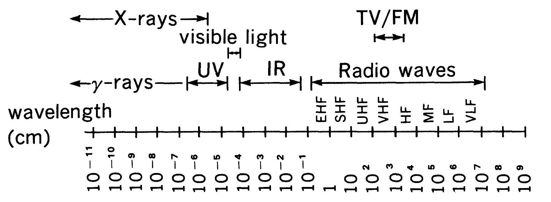 Fig. 1 Spectrum of Electromagnetic Waves
In general, all material can be considered as sources of heat. There is a known relationship between the wavelength of the strongest infrared radiation and the temperature of the material emitting it. This relationship is called Wien’s displacement law, and the total energy value can be derived from Stefan–Boltzmann law (Figure 2).
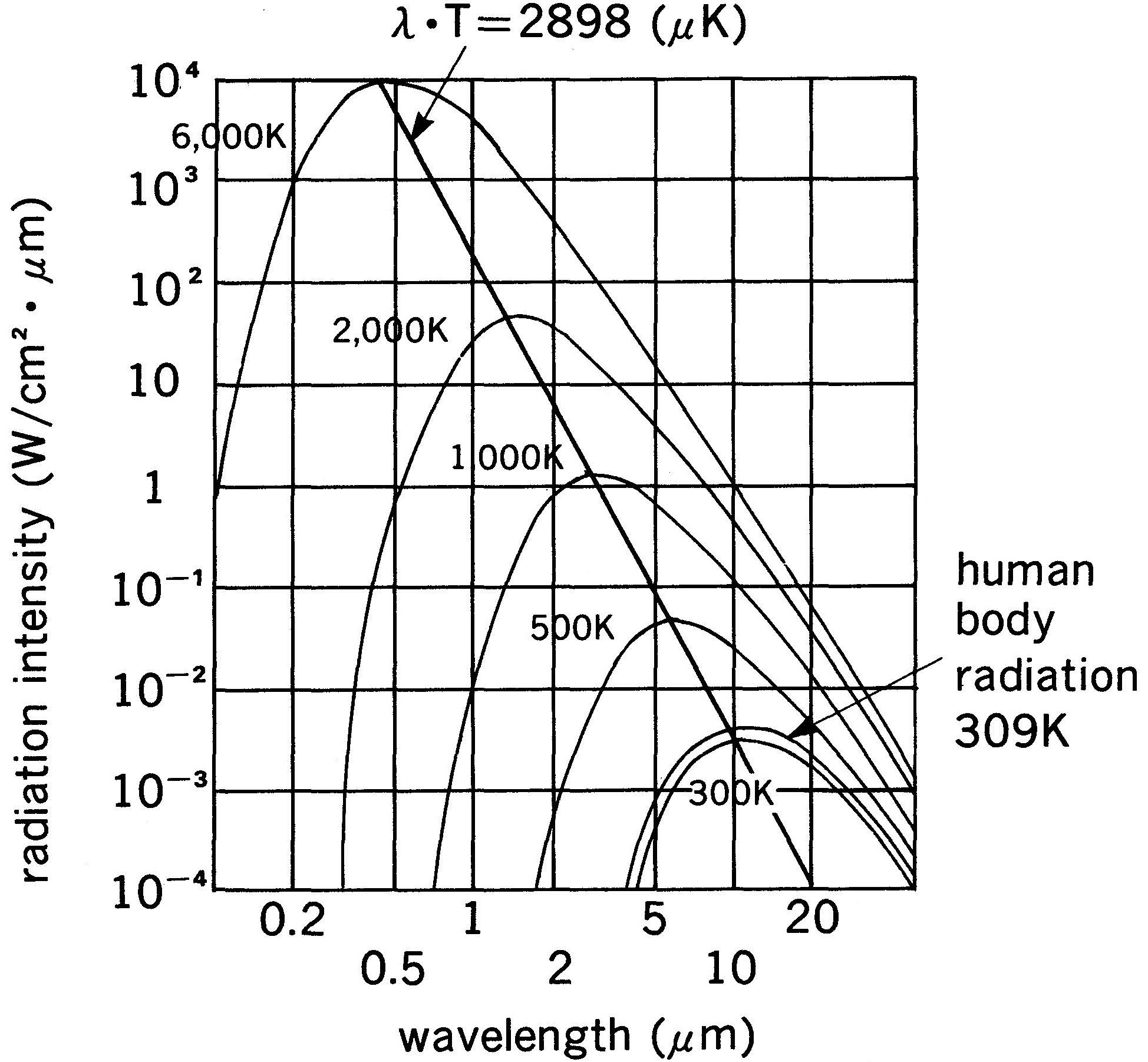 Fig. 2 Temperature of Object and Wavelength of Radiated Energy
The human body, for example, has a normal temperature of about 36°C (309K). As shown in Figure 2, the strongest radiation at this temperature is 9.4μm. Other wavelengths are radiated as well of course, but as shown in the figure, these other wavelengths are greatly attenuated as they move away from 9.4μm.
Knowing this characteristic of the human body allows us to identify it if we can detect around 9.4μm radiation (note that other animals and materials can also radiate at this wavelength.). PIR sensors are used to passively detect these infrared rays. Among them, Pyro Sensor is a sensor for human sensation that selectively and stably captures the human body in a wide area.
Pyroelectric Effect and Sensor Configuration
The detection of infrared radiation by Pyro Sensor is based on a physical phenomenon called the pyroelectric effect. Certain type of material will generate a surface electric charge when exposed to heat. This effect is based on the polarization phenomena of dielectric materials. In some dielectric materials, polarization depends of hysteresis, and they are spontaneously polarized without the application of an external electric field. These materials are called ferroelectrics.
As shown in Figure 3, when the material is in thermal equilibrium, an electric charge is continually being generated on the surface due to the spontaneous polarization effect. And this charge is just as quickly dissipated, because the material surfaces are exposed to opposite charge floating around them.
Because spontaneous polarization depends on material temperature, it varies when the temperature shifts from T[K] to T+ΔT[K]. The surface charge cannot follow this rapid change in spontaneous polarization, and for a short period of time we can observe this difference in charge. The current flowing during this time is called Pyroelectric Current.
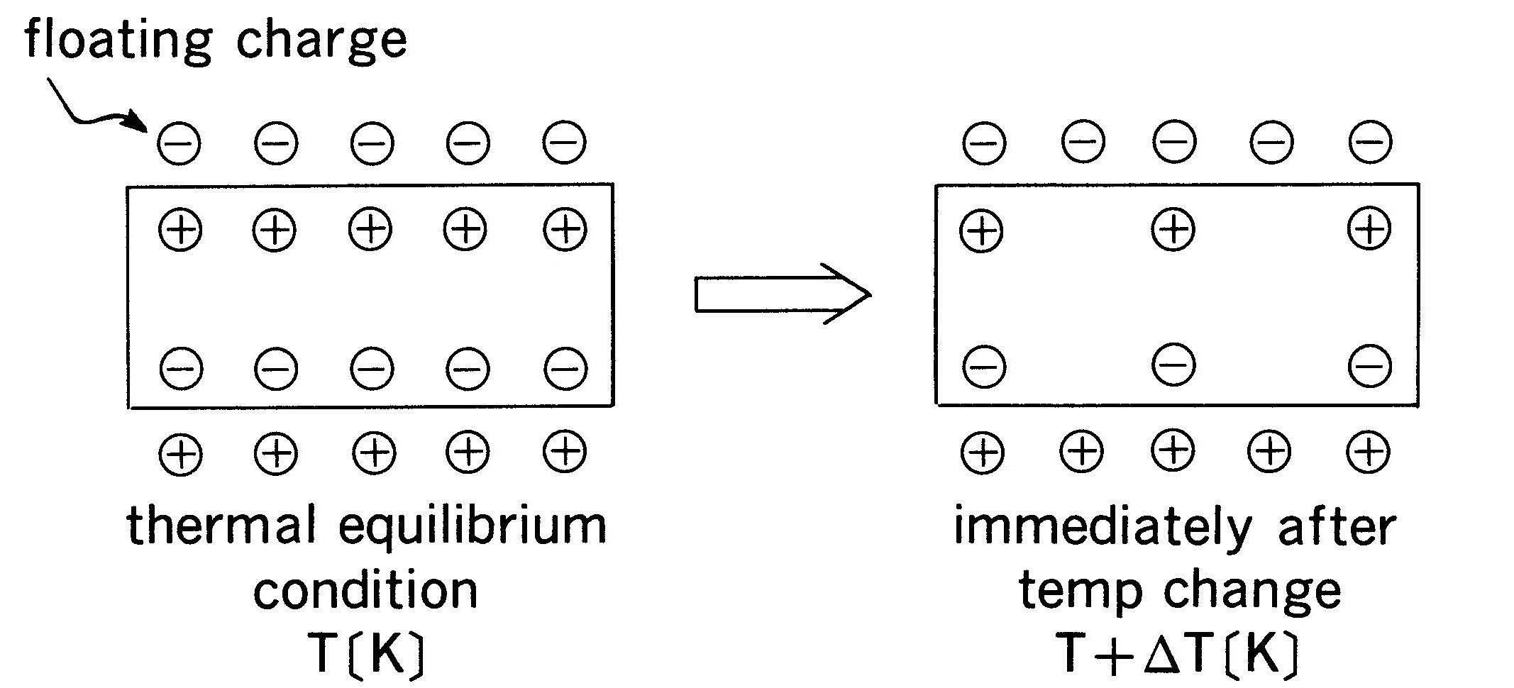 Fig. 3 Change of Pyroelectric Material Surface Charge
The Pyroelectric Current can be measured by connecting a high impedance resistor between the electrodes on both material surfaces and reading the voltage change. This basic circuit is shown in Figure 4.
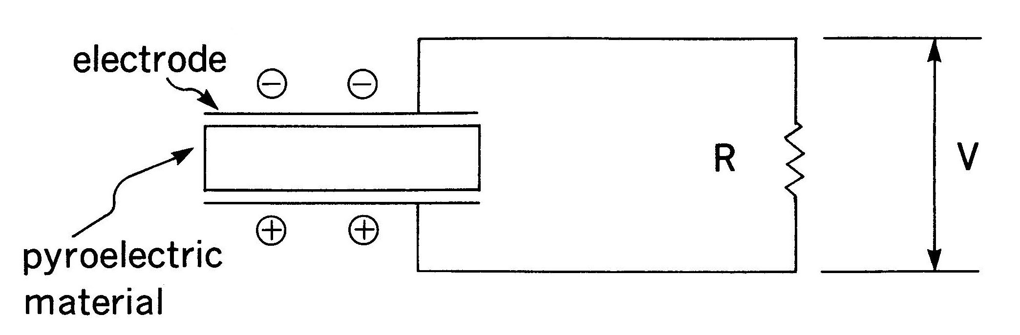 Fig. 4 Output Measurement
By applying an external electric field, the direction of the spontaneous polarization of the ferroelectric material can be changed. The material can be uni-poled to exhibit a large pyroelectric effect. There are many suitable ferroelectric materials that will generate a comparatively great amount of surface charge per unit of temperature. This characteristic is called the Pyroelectric Coefficient.
NiCeRa PIR sensors use Polycrystalline fine ceramics. Developed over many years of research, it provides large Pyroelectric Coefficient in around 9.4μm area of interest used to detect the infrared radiation from the human body.
Rg and FET
Fabricating a usable PIR sensor begins with processing the appropriate ferroelectric material to proper size chip and attaching electrodes on both sides to carry the Pyroelectric Current.
As illustrated in Figure 4, a resistor is connected across the electrodes, and the current is read as a voltage change across this resistance. Since the infrared radiation from human body is very small, it creates a correspondingly small current on the detector. The resistance must be very large to generate a convenient voltage level.
To read out the voltage across such a high resistance requires an even higher resistance to avoid current leakage to the volt meter. In practice it is hard to find such a high resistance. To overcome this problem, impedance transformation is used to get to a resistance value that easier to handle.
As shown in Figure 5, the general scheme is to use an FET (Field Effect Transistor), which provides small leakage current and a high input impedance. The resistor across the sensor electrodes is called Rg because it is connected to the FET’s Gate terminal. A power source of about 1.0 ~ 15VDC is applied to the Drain terminal. Once the Pyroelectric Effect is noted, the Drain-Source channel is controlled by the Rg voltage and the Source voltage (Vs) is varied. This is a source-follower configuration. The Pyroelectric Effect is then measured by reading out the change in Vs when a proper resistor (Rs) is between the Source and Ground terminals.
Putting a threshold on a downstream circuit is useful as a switching device. Rg and the FET are inside the sensor housing, The Source resistor is normally about 470kΩ, although it can be varied within a specified range to accommodate customer applications.
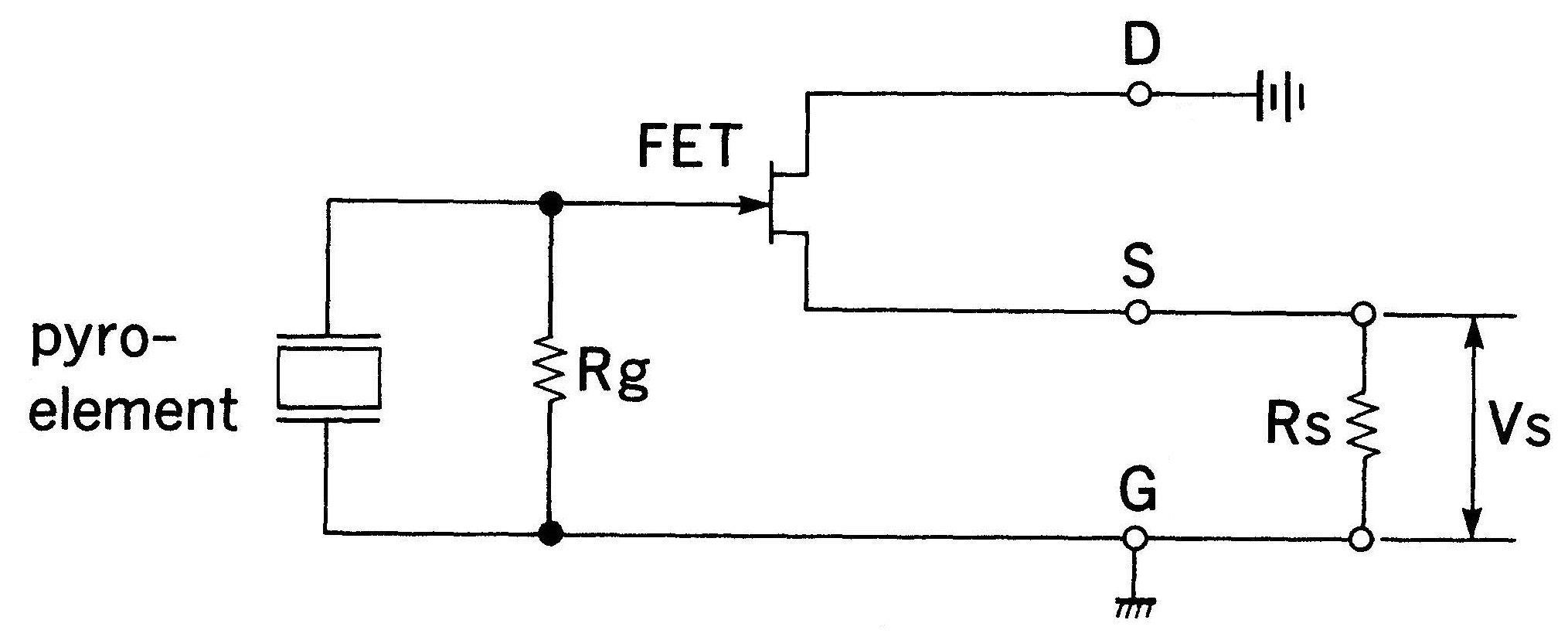 Fig. 5 Pyro Sensor Internal Circuit
Optical Filter
The pyroelectric chip circuit itself is relatively non-selective in terms of its response to infrared radiation of various wavelengths. The same temperature change generated by 9.4μm can also be created by a number of other wavelengths as well.
In order to target the 9.4μm radiation emitted by a human body, the incoming radiation must be selectively filtered, using an optical filter in front of the chip. In practice, an optical filter with a bandpass of approximately 5~14μm provides adequate S/N ratio. Figure 6 illustrates the transmission characteristics of a typical cut-on filter for this range.
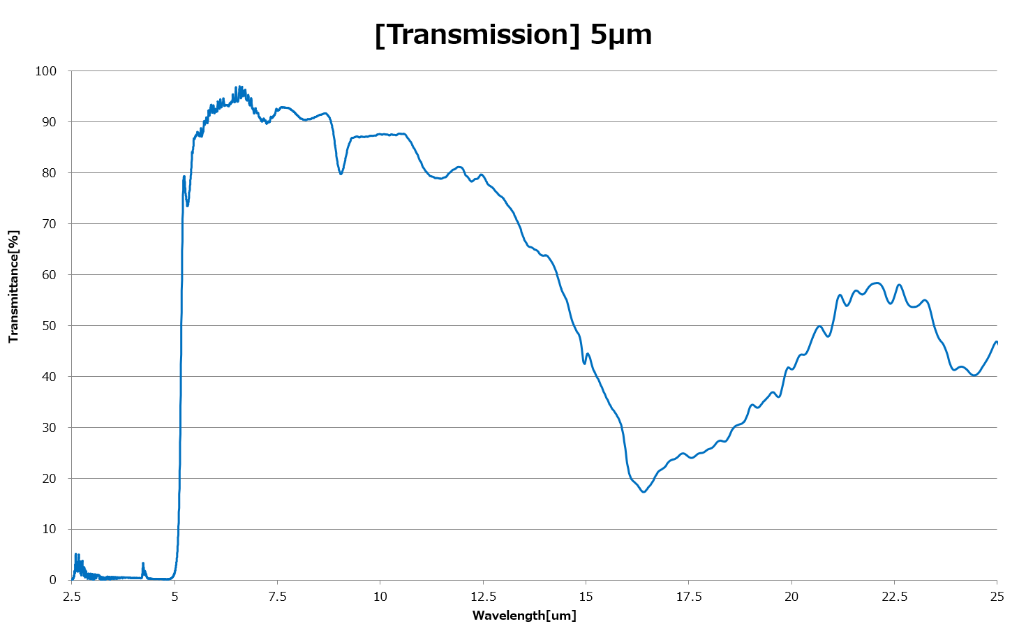
Fig. 6 Filter Transmission Characteristic (5.0µm cut-on)
Structure
Figure 7 shows the physical structure of a typical infrared sensor and its equivalent circuit. This typical sensor is composed of:
- a pyroelectric chip to absorb infrared radiation.
- an infrared filter
- Rg (gate resistor) to change the Pyroelectric Current into a voltage signal
- an FET for impedance transformation
- a protective housing
Electrodes are formed on both surfaces of the chip. The electrode pattern on the infrared absorbing side of the chip can be varied by application, and may have one, two or more elements.
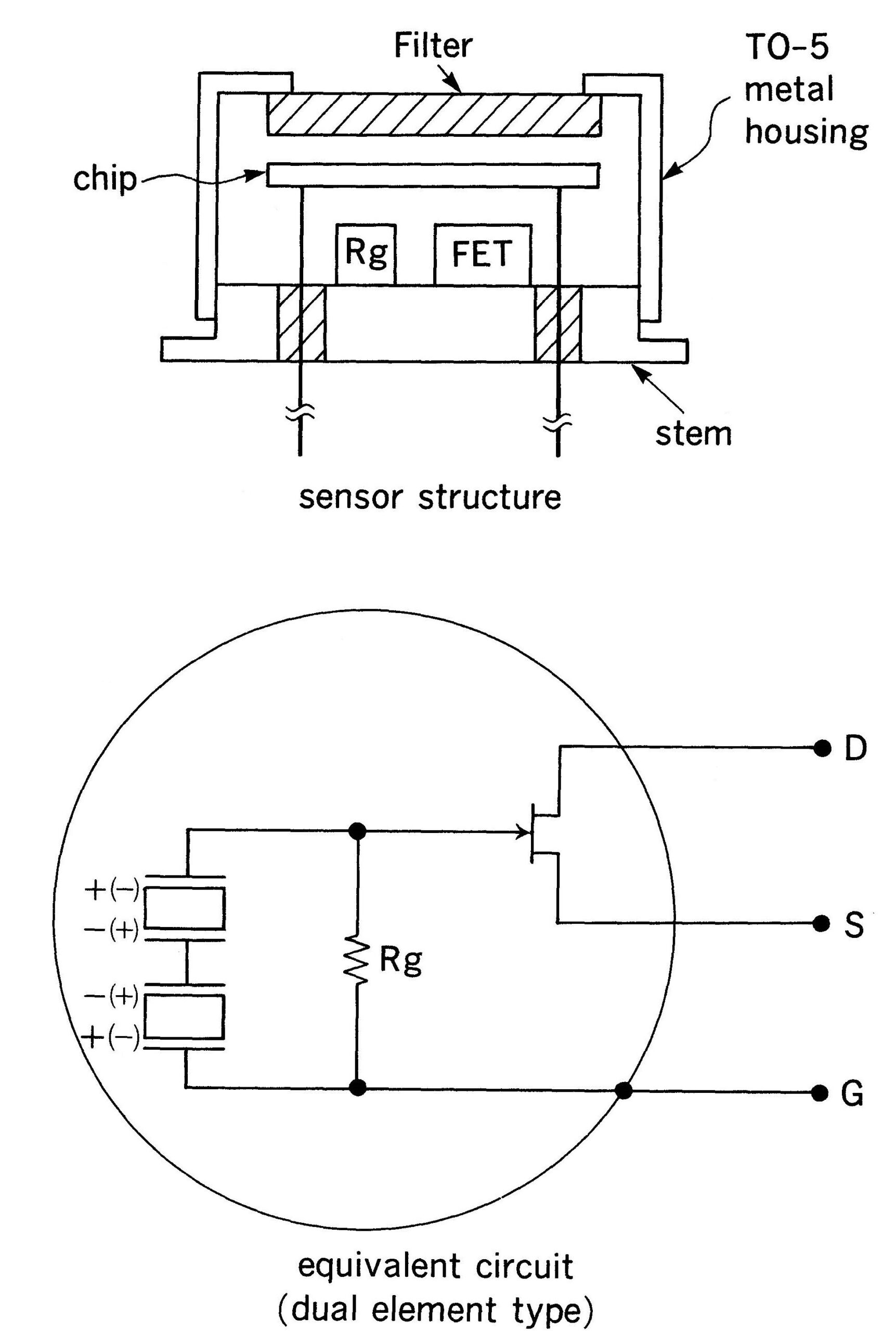 Fig. 7 Structure & Equivalent Circuit
2. Types
Single Element Type
The current NiCeRa single element sensor is greatly improved compared to earlier versions, which suffered from failure due to vibration and from source voltage fluctuations due to sudden temperature changes. It is used to detect flames, gas concentration, overheating of house fixtures, etc.
Dual Element Type
This type is most often used as a sensor for human body detection. It has two elements in a series-opposed configuration. Error signals caused by ambient temperature change, vibration, or external optical noise from sunlight or lamps are almost completely cancelled. Because of this very high reliability, this is the sensor type of choice for security application, lighting control, home appliance control, etc.
Quad Element Type (One Output)
This quad element sensor has four subdivided detection areas and is typically mounted on a ceiling to detect human body as occupancy sensor or presence detection since the four small detection areas can detect tiny movement of human body.
Quad Element Type (Two Outputs)
This type can distinguish between the human body and small animals because we can obtain more information from two sets of dual element. It is typically used to high-end security application with the PET immunity performance.
Omni-directional Dual Element Type / 69-PyroTM
This special shape dual element type is an omni-directional type and it can be installed anywhere and in any direction. It has also higher sensitivity even in the direction toward the sensor. This is most suitable for passing detection for ceiling mount applications.
SMD Type / S-PyroTM
SMD support for various types of pyroelectric infrared sensors is available. It supports security-grade EMC and white light immunity that could not be obtained with conventional SMD type.
Digital Communication Type / D-PyroTM
With the built-in dedicated ASIC, communication by UART or I2C is available. It is also possible to simply output an ON/OFF signal. As a result, all analog circuits can be omitted, and you can connect directly to your MCU.
3. Applications
Amplifier
The use of an op-amp provides two methods of signal amplification. Figure 8(a) shows an inversion amplifier, while Figure 8(b) details a non-inversion amplifier.
In the inversion amplifier scheme, power supply voltage is set using voltage divider network, R2/R3 in the schematic. This allows almost any source voltage to be used to drive the circuit. Since the circuit input impedance is determined by R1 (usually 1k ~ 10kΩ) the amplifier will exhibit low input impedance.
In the case of non-inversion amplification, the circuit will have a much higher input impedance (on the order to several MΩ) because the op-amp it self determines the circuit input impedance. However, Vs must be some minimum level because it determines the operating voltage of the amplifier. Too low a Vs and the amp may not operate.
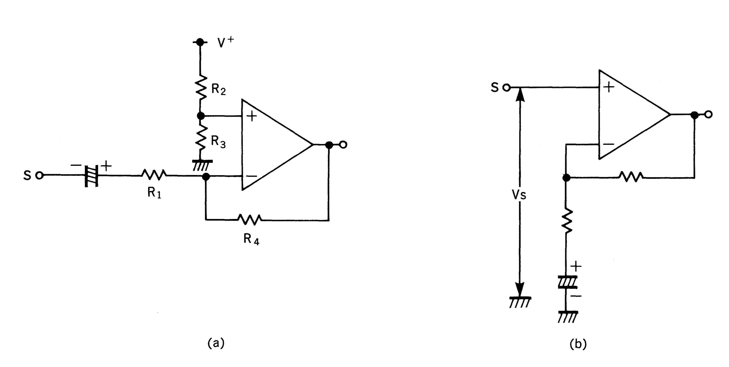
Fig. 8 Operational Amplifier
Circuit Example
Figure 9 shows a typical application circuit, consisting of an amplifier, a comparator, a timer and a relay driver.
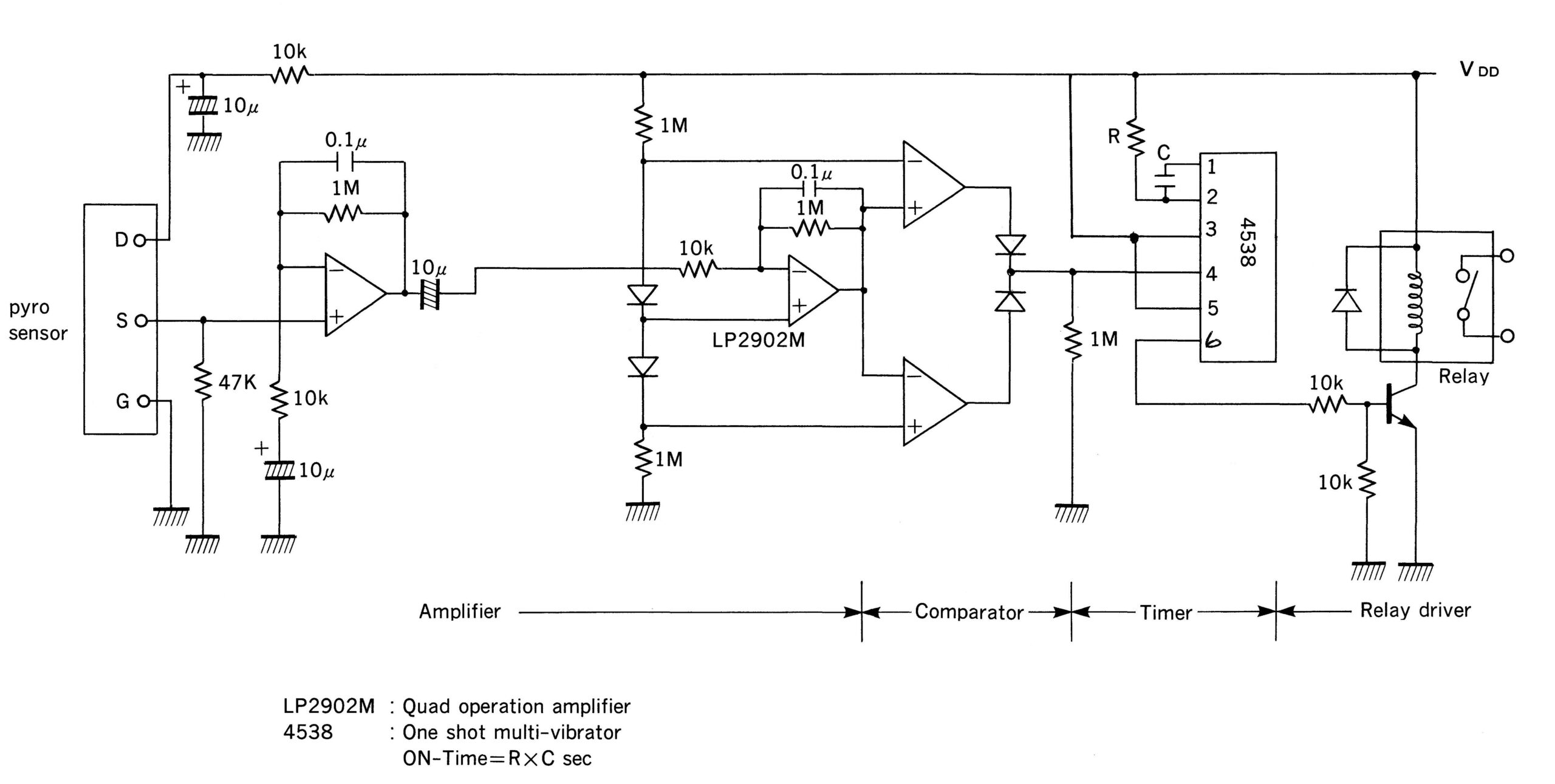
Fig. 9 Typical Application Circuit