1.How It Works
Hall element is a magnetic sensor utilizing Hall effect. Hall effect is based on the principal that a difference of electric potential is generated in perpendicular direction to both of the electric current direction and the magnetic flux direction when the electric current flows through the solid (semiconductor thin film) and the magnetic field in the direction vertical to the solid surface is applied. The figure [1-1] illustrates the basic principal of the Hall element. Hall voltage, VHM, can be represented by the following equation (1) or (2).
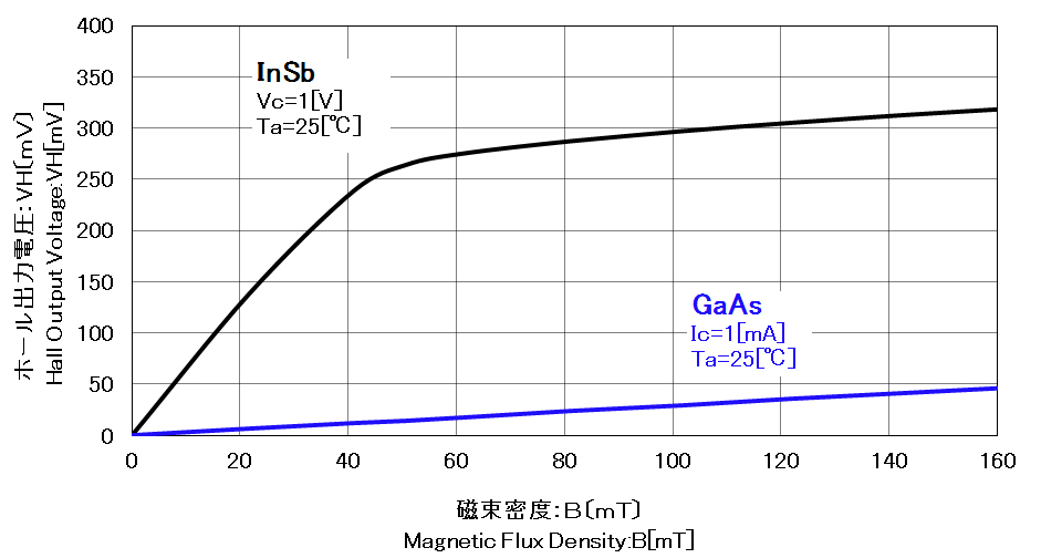
2.Characteristics of Hall Element
Figure [2-1] presents the relationship between Hall output voltage and magnetic flux density. InSb type Hall element has a high sensitivity to the magnetic field, and can detect weak magnetic flux density. GaAs type Hall element has a relatively low sensitivity, but has an excellent linearity with respect to the magnetic field.
3. Features of InSb Type
- Ultra-high sensitivity.
- Ultra-small package makes possible the miniaturization and thinner.
- Compatible terminal layout with market standard Hall elements.
- Vertical SMD type (vertical magnetic sensitive surface to PCB surface) is available, which is unique package in the market.
- Packing with a tape and reel for automatic assembly is available.
- Axial type is available.
4. Features of GaAs Type
- Low dependency of Hall voltage to ambient temperature, and it changes linearly according to the temperature.
- Wide operation temperature range (-40℃ 〜 +125℃)
- Excellent linearity of Hall voltage to the magnetic flux density.
- Low temperature dependence of offset voltage.
5. Applications
- Brushless DC motors (Fan motor, 3-phase BLDC motor)
- Position detection sensors
- Number- of -rotation detection sensors
- Current sensors
- Other magnetic sensors
6. Notes
- Soldering conditions
- Notes on absolute maximum rating
- Notes on the storage
- Notes on handling
- Notes on electrostatic discharge
Soldering conditions
(1)Recommended Soldering Conditions
| Method | Temperature |
|---|---|
| Reflow Soldering | MAX. 260℃, 10sec. |
| Soldering Iron | MAX. 350℃, 3sec. |
- In the reflow soldering, please avoid rapid heating, and rapid cooling from the Hall element.
- Please refer to the below temperature profile for pre-heating of the reflow soldering.
- Recommended duration and the peak temperature are about 5 seconds and 245 〜 260℃ in the reflow soldering.
- Iron tip should be prevented from touching with Hall element in soldering iron method.
(2)Temperature Profiles
[Reflow Soldering]
Absolute Maximum Rating
The use of Hall element over absolute maximum ratings may cause the failure.
Storage
The performance of Hall element may be affected by the storage conditions.
Storage Hall element in the following conditions may cause to the appearance damage, defective performance and poor solderability;
- a. Direct sunlight, high temperature and humidity, or rapid temperature changes conditions
- b. Corrosive gas, organic gas, or acidic/alkaline atmosphere
- c. Dusty environment
Handling
Note the following cautions;
- a. Do not incinerate, destroy, crush or decompose chemically the product.
∗Especially, do not conduct the incineration or reaction with acids/alkalis as they may cause hazardous gas. - b. Should not be put in the mouth.
- c. When Hall elements are disposed of, they must be burned or buried by an industrial waste vendor with the appropriate licenses.
Electrostatic Discharge
During handling the product, the operator should be properly grounded with earth band etc.
Facilities and equipment should be also grounded correctly, and ensure that the accumulation of static electricity does not occur.
Use the charge neutralizer when nonconductor and Hall element are touching.