NiCeRa’s thermopile type infrared sensors (Thermopile Sensor) have been widely adopted in markets around the world, mainly for body temperature measuring devices such as human body temperature detection and heating and cooling devices for indoor temperature measurement.
Furthermore, its use in consumer equipment such as vehicle air conditioners, OA equipment, microwave ovens, and IH cooking heaters is expanding.
In addition to responding to various demands, NiCeRa is promoting high quality, high functionality, and low cost of Thermopile Sensors that NiCeRa has traditionally achieved through research and development.
This site introduces the basic principles and application examples of NiCeRa’s Thermopile Sensors.
Chapter 1 explains infrared rays, Chapter 2 explains thermopile sensors, and Chapter 3 introduces application examples.
1. Infrared Ray
About Infrared Ray
The brilliant sunlight, the radio waves that send information on TVs and radios, the radio waves of mobile phones, wireless LANs, cordless telephones, and the signals of remote controls for electrical appliances are all called electromagnetic waves.
These electromagnetic waves are only different in wavelength (frequency).
See Figure 1. It shows how electromagnetic waves are classified according to the difference in wavelength.
Infrared rays are part of electromagnetic waves as well and have wavelengths from 0.78μm to 1mm. Infrared ray has a longer wavelength than visible light and is invisible to the naked eye. Incidentally, those with shorter wavelength than visible light is called ultraviolet rays.
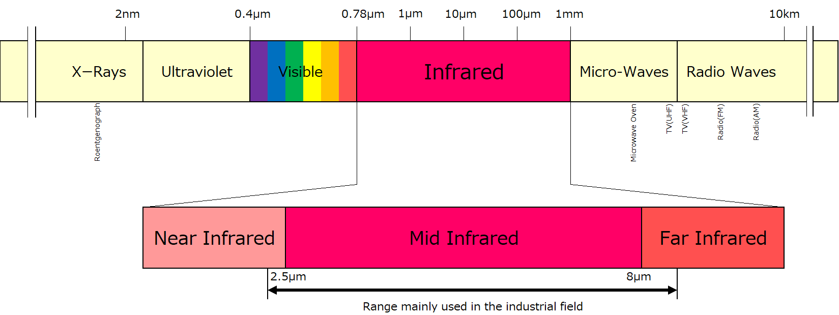
Fig 1: Electromagnetic Wave Spectrum
Temperature and Thermal Energy
Everyone knows empirically that when a hot object touches a cold object, the heat of the hot object gradually decreases, while the temperature of the cold object gradually increases. So why do the temperatures of the two substances change? That is because thermal energy is transferred from hot object to cold object. Thermal energy is the total amount of kinetic energy of atoms and molecules of a substance. The fact that an object has temperature can be translated into the fact that the object has thermal energy. Thermal energy moves from high to low between substances with different thermal energies. In cold objects, the movement of atoms and molecules becomes inactive, resulting in lower thermal energy. By heating the object, new heat energy is given to the object, and the movement of atoms and molecules of the object becomes active and the heat energy increases. It is possible to measure changes in temperature by measuring changes in the thermal energy of such objects (Figure 2).
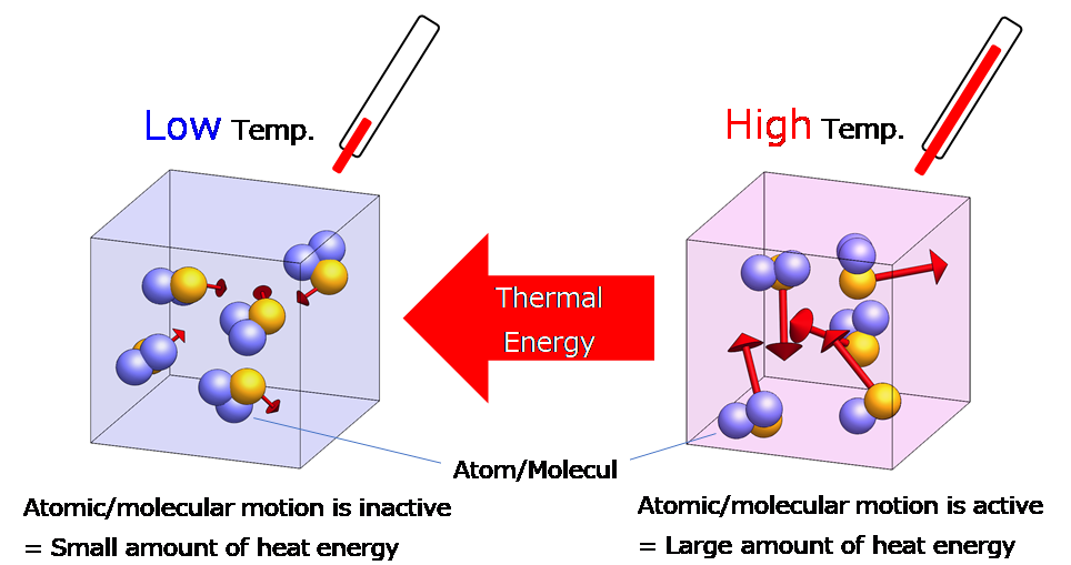
Fig 2: Temperature and Thermal Energy
Heat Transfer
Heat moves from high to low, and there are three types of transmission “conduction,” “convection,” and “radiation” as follows. Thermopile Sensors are used for temperature detection using radiation.
Conduction
When you hold the pocket heater with cold hands, the hand holding the pocket heater gets warmer and warmer. The movement of the temperature of a solid or liquid that comes into contact in this way from higher to lower is called conduction. Contact thermometers and the like take advantage of this property.
Convection
When you warm the lukewarm bath again, the whole hot water will gradually warm up. This is due to convection. Warm water or air becomes lighter and rises, and cold water or air becomes heavier and falls. Heat is transferred by the flow.
Radiation
Typical heat radiation is felt when exposed to sunlight, stoves, bonfires and so on. This is because the sun and others radiate heat energy as infrared rays. Every object emits infrared rays, and the higher the temperature, the higher the amount of radiation. Thermopile Sensors measure the temperature of a substance by measuring such infrared radiant energy.
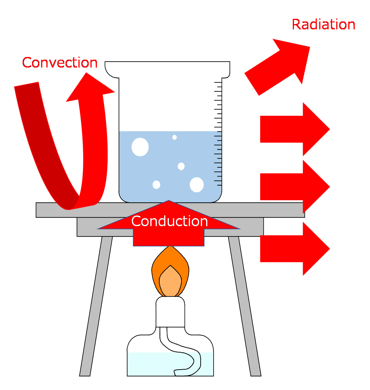 Fig 3: Heat Transfer
Infrared Radiation / Absorption / Reflection
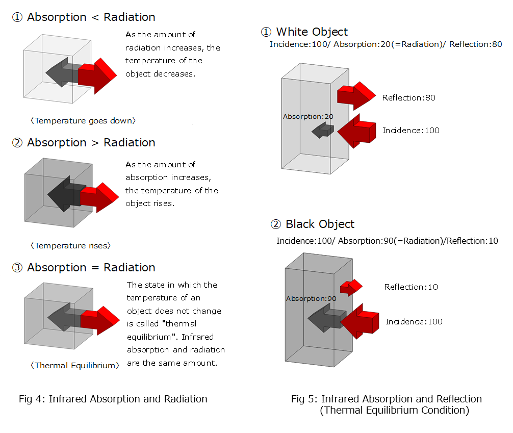
Every object emits infrared energy, at the same time it also absorbs infrared energy from other objects. Absorbing infrared rays raises the temperature of an object, and radiating it lowers it. Figure 4 shows the relationship between the radiation and absorption of infrared energy and the temperature of each.
Objects not only absorb infrared energy from the other objects, but also reflect it.
In the visible region, those that reflect light well appear white and those that absorb it well appear black. Similarly, in the infrared region, objects that reflect infrared rays well are called “white objects”, and objects that absorb infrared rays well are called “black objects”. The relationship shown in Figure 5 holds for any object.
Perfect Blackbody
White objects and black objects were explained in the previous chapter. Among them, an object that absorbs all kinds of light is called a perfect blackbody.
The principle that the amount of infrared radiation and the amount of absorption are the same in the thermal equilibrium state, and the reflection and absorption of infrared rays in Figure 5 are combined to show the relationship in Figure 6.
An object that absorbs infrared rays well emits more infrared rays. A perfect blackbody absorbs all light, it therefore emits more infrared ray than other objects at the same temperature.
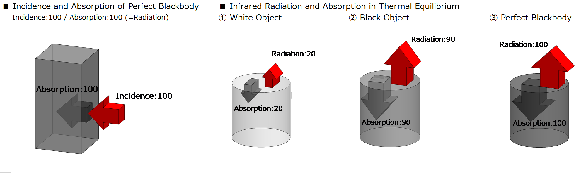
Fig 6: Relationship between Surface Condition and Incident / Absorption / Radiation
Infrared Radiant Energy
The amount of infrared radiation emitted by a blackbody is determined by the relationship between the wavelength of light and the temperature. This is called Planck’s law. See Figure 7. Numerical values such as 6000K and 3000K represent the temperature of the object. The horizontal axis of the graph represents the wavelength of light, and the wavelength becomes longer toward the right. The vertical axis represents the amount of light (radiant amount). From this graph, we can see that the higher the temperature, the more light is emitted. When the temperature reaches about 1000K, it emits visible light and appears to glow red. It will emit light with a shorter wavelength as it goes up to 2000K and 3000K. That is why the higher the temperature of the flame, the bluer it looks (visible light with a shorter wavelength). We can see that the temperature of the object can be obtained from this graph if the emissivity of infrared rays is known.
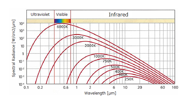 Fig 7: Blackbody Radiation Spectrum
Emissivity
The temperature of a perfect blackbody is determined by the wavelength and amount of infrared rays, but in reality, the amount of infrared rays emitted differs depending on the material and surface condition of an object even if the same temperature. A normal object emits less infrared ray than a perfect blackbody.
The ratio of the amount of radiation between a perfect blackbody and an actual object is called emissivity and is represented by the symbol ε (epsilon). The emissivity of all normal objects is less than 1 since the emissivity of a perfect blackbody is 1. The same material may not always have the same emissivity because the emissivity varies depending on the conditions such as wavelength, temperature, and surface condition.
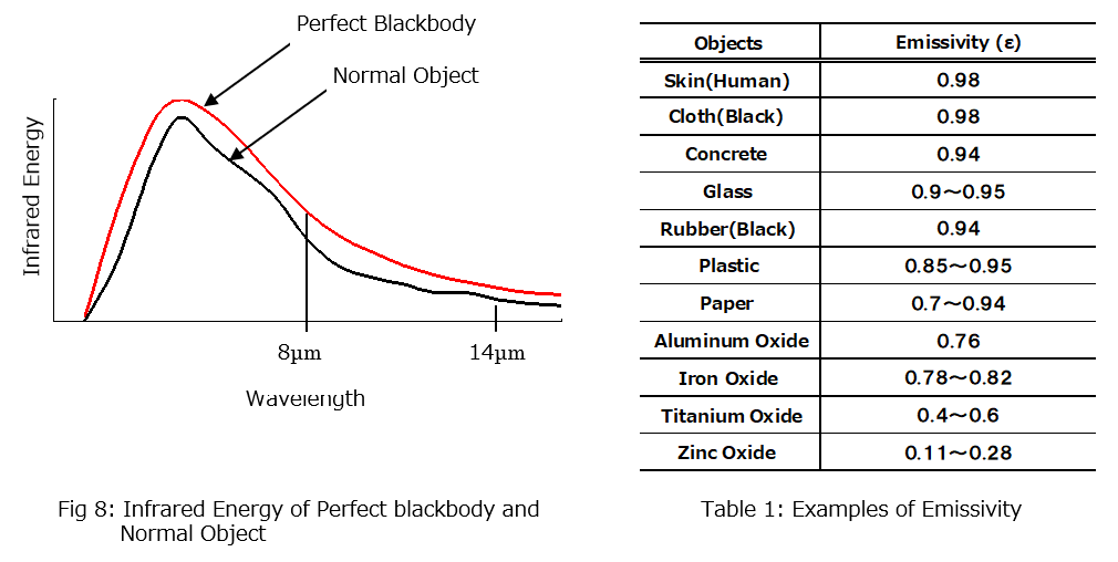

Fig 9: Relationship between Emissivity and Reflectance
2. Thermopile Sensor
About Thermopile Sensor
The Thermopile Sensor is one of the thermal infrared detectors and has the following features.
・Operates at room temperature
・Broadband spectral sensitivity characteristics
・No need for optical chopping
・Low Cost
・Long Life
The Thermopile Sensor uses the Seebeck effect to generate a thermoelectromotive force proportional to the amount of incident energy of infrared rays. The Thermopile Sensor element itself does not have a large wavelength dependence. It is used for applications such as temperature measurement, human body detection, and gas analysis, by using various window materials.
The elements of NiCeRa’s Thermopile Sensor connect a large number of thermocouples in series on a silicon substrate in order to obtain a large output voltage, maximizing the temperature difference between hot and cold junctions. The heat separation structure is formed between the hot junctions and the cold junctions, and an infrared absorption film is attached on it. The heat separation structure is realized by forming a membrane (thin film) using MEMS technology. The thermocouple uses a material that has a large Seebeck coefficient (thermoelectromotive force) and can be formed by a semiconductor process.
When infrared rays are incident, the light receiving film (hot junctions) on the membrane warms up, creating a temperature difference [ΔT] with the cold junctions, and the resulting thermoelectromotive force [ΔV] can be obtained, by abovementioned structures.
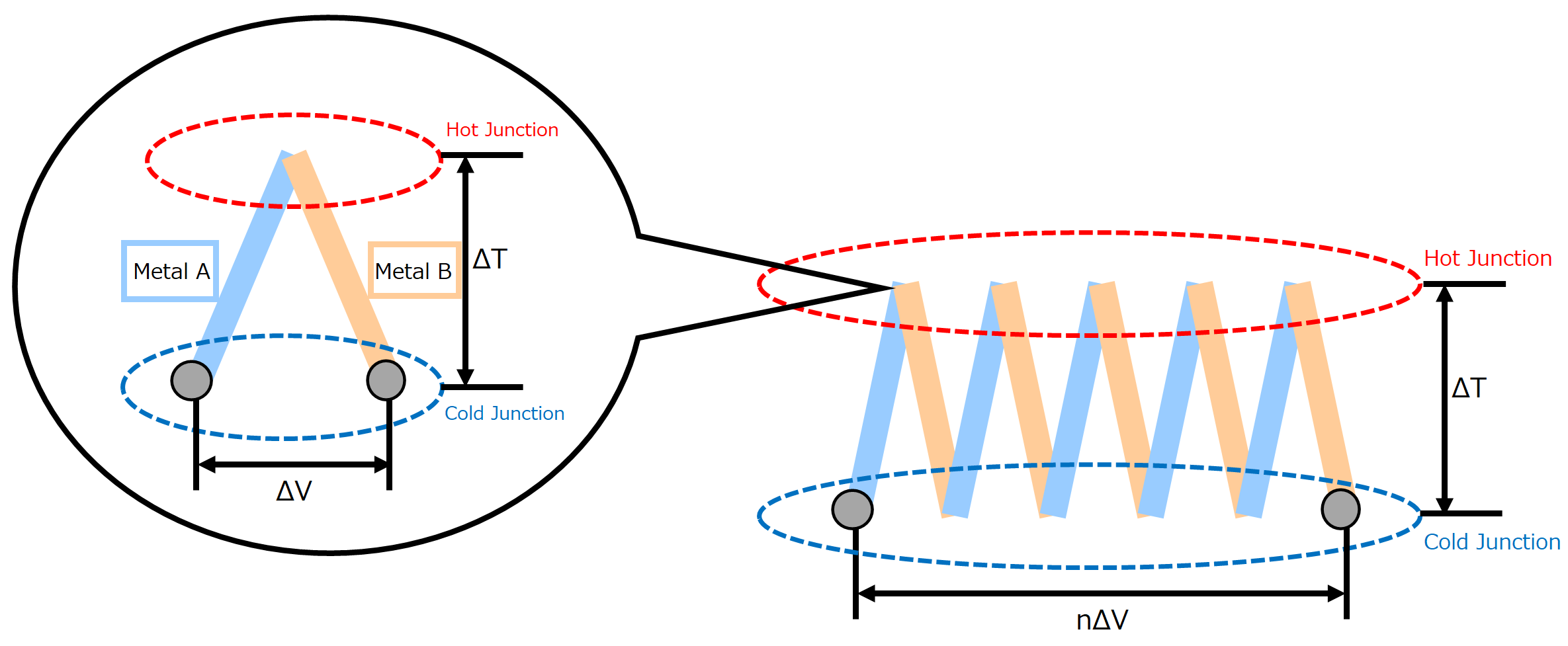
Fig 10: Thermopile Sensor Element Structure
Structure
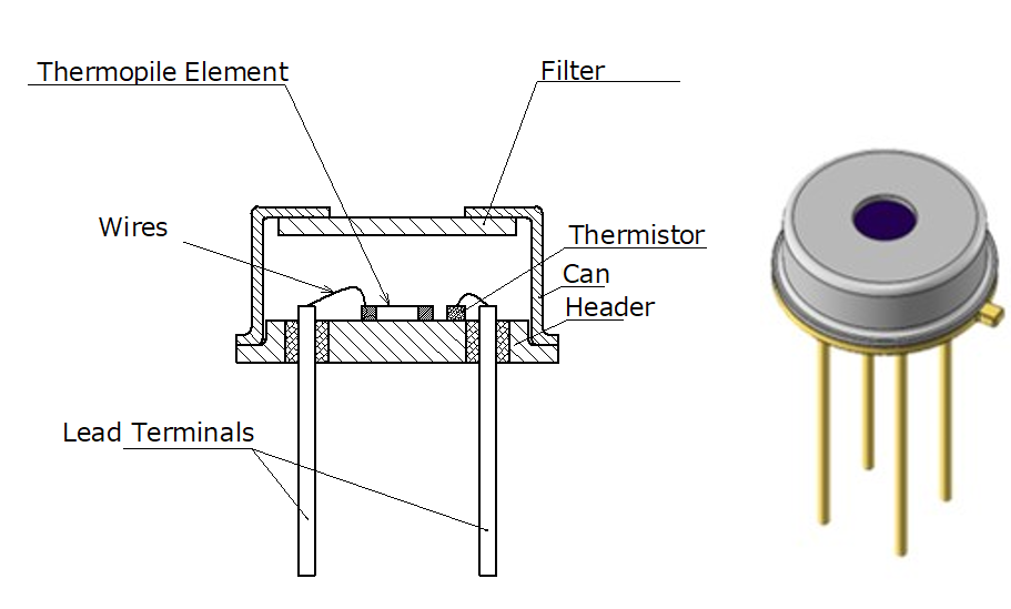 Fig 11: Sectional Structure
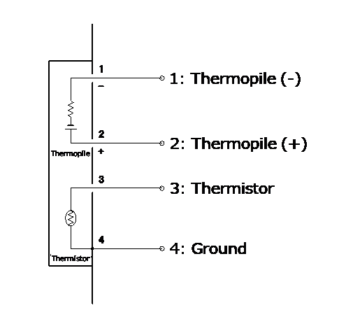 Fig 12: Equivalent Circuit Schematic
Thermopile Element
The light receiving thin film part is configured on the central diaphragm formed by silicon micromachining technology.
The thermopile element is formed by an infrared absorbing film, a thermocouple, a hot junction (on center thin film part), and a cold junction (on heat sink part).
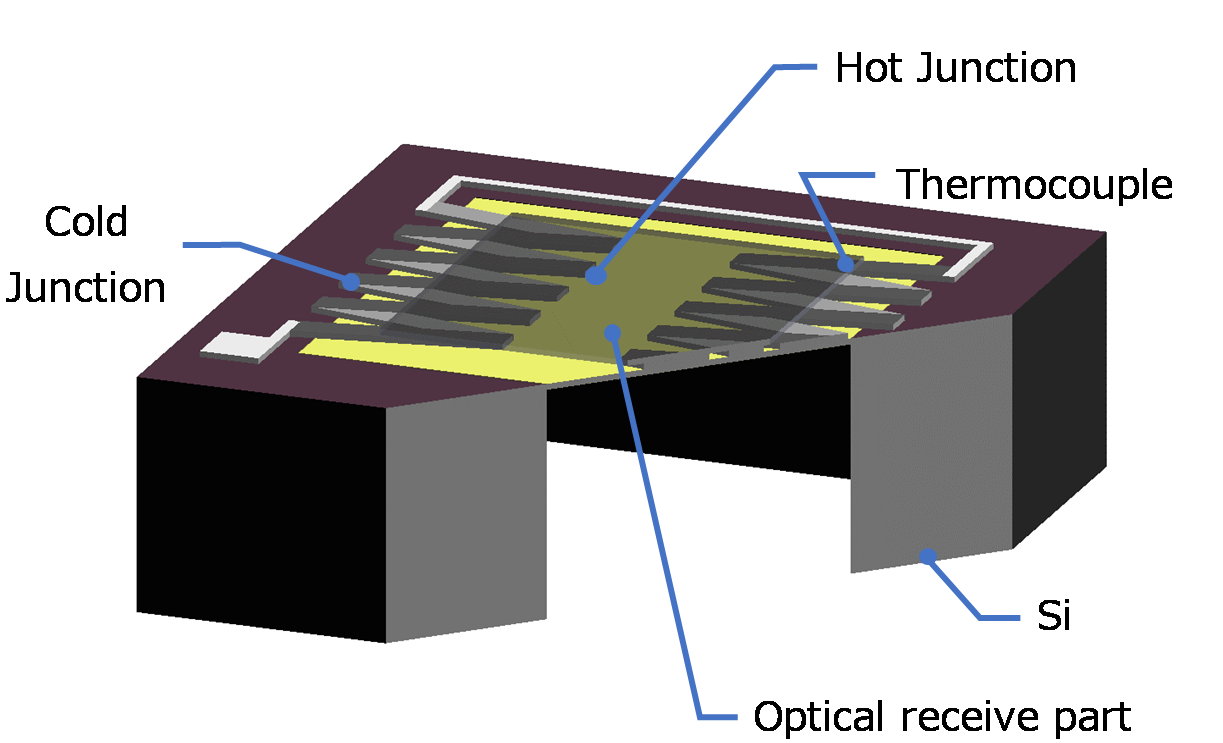
Fig 13: Thermopile Element
Thermoelectromotive Force and Thermocouple
When two different metal materials are connected to form one circuit (thermocouple) and a temperature difference is applied to the two contacts, a voltage is generated in the circuit. This phenomenon was discovered by the German physicist Thomas Seebeck in 1821 and is called the Seebeck effect.
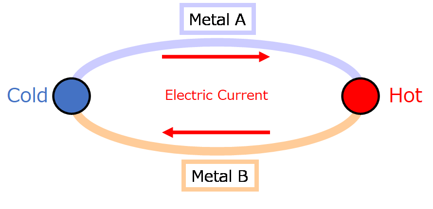 Fig 14: Seebeck Effect
If one end of this circuit is opened, it can be detected as a potential difference (thermoelectromotive force).
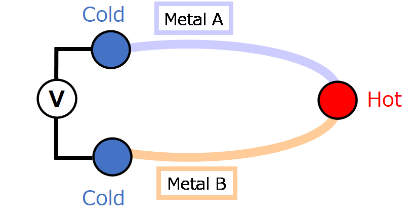 Fig 15: Thermoelectromotive Force
The thermoelectromotive force depends on the type of metal to be combined and the temperature difference between the two contacts, but not on the shape and size of the two constituent metals. Many temperature detecting elements have been developed to take advantage of this phenomenon. The temperature detecting element that utilizes this phenomenon is generally called a thermocouple.
Basic Characteristics and Terms
Number of Element
■Single Element
Thermopile with one detection area. The average temperature in the detection area can be detected since the radiant energy in the detection area is averaged. It is used in ear thermometers, forehead thermometers, various home appliances, etc.
■Dual Element
Thermopile with two detection areas. The radiant energy of each of the two detection areas can be measured and compared. It is used for gas detection, etc.
■Multi Element
Thermopile with two detection areas. The radiant energy of each of the two detection areas can be measured and compared. It is used for gas detection, etc.
Optical System
■Filter
It is generally used when a wide viewing angle is required. The radiant energy obtained is large and the output sensitivity is also large since it detects a wide angle.
High flexibility in coating to provide the required optical properties. Mainly for single element type.
■Lens
It is generally used when a narrow viewing angle is required. It is possible to design according to the number of elements and the detection angle.
The radiant energy obtained is small and the sensitivity output is small, due to the narrow angle detection.
Detection Wavelength
The thermopile Sensor detects the infrared range in electromagnetic waves. Infrared rays are electromagnetic waves in the wavelength range of 0.78μm to 1mm, which have a longer wavelength than visible light and a shorter wavelength than microwaves. Infrared rays are not only the properties of electromagnetic waves, but also the thermal energy generated from all objects with temperatures above absolute zero.
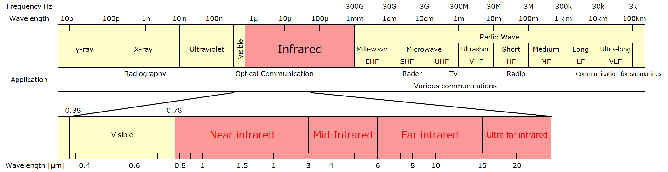 Fig 16: Detection Range of Thermopile Sensor
3. Application
Measurement Temperature Range
The temperature range of an object that can be measured by a Thermopile Sensor.
The Thermopile Sensor generates an electromotive force by the radiant energy received from the object to be measured. Its electromotive force is a few millivolts, so it is difficult to read as it is. The minute output is amplified by an amplifier circuit to make it easy to read. At this time, the full scale of the output is determined by the supply voltage to the amplifier circuit. For example, if the supply voltage is 5V, the output will be saturated there, making it impossible to detect the temperature of the object beyond that. Therefore, the required temperature detection is possible by determining the amplification factor of the sensor according to the measurement temperature range and the full-scale voltage.
Signal Output and Measuring Method
The output of the sensor is called the output voltage (Sensitivity) and is expressed in units of voltage (mV). For instance, if the heat source is 100°C and the ambient temperature is 25°C, the output voltage will be about 12 mV or less, although it depends on the sensor type. When the heat source is 25°C and the environmental temperature is 25°C, the output voltage is 0mV because the electromotive force is zero regardless of the sensor type.
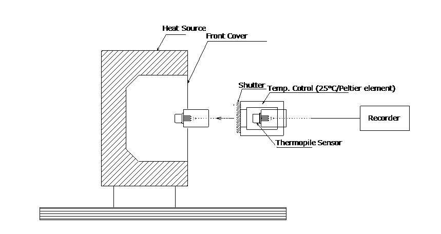 Fig 17: Measurement Condition
Detection Viewing Angle (Field of View/FOV
The field of view that can be detected by the thermopile sensor is represented by an angle. It is an angle that has a sensitivity of 10% or more when the sensitivity in front is 100%.
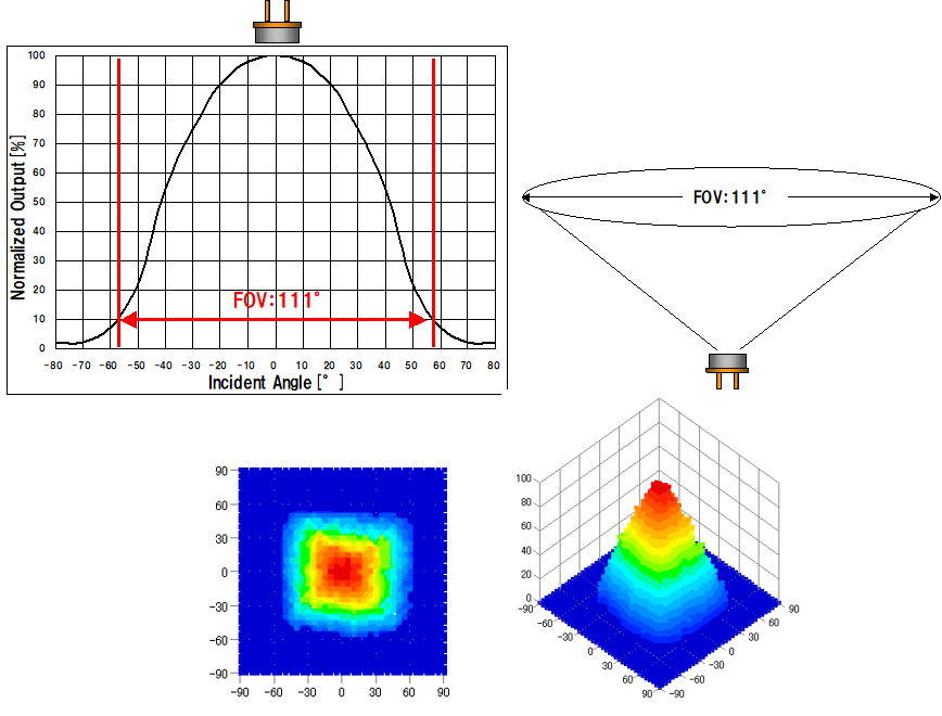
Fig 18: Detection Viewing Angle (FOV)
Arithmetic Mean
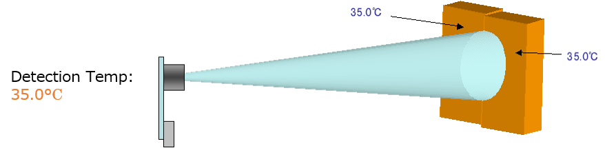
The Thermopile Sensor detects the radiant energy in the detection area as the arithmetic mean.
For example, if the detection area is all constant at 35.0°C, the detection temperature will be 35.0°C.
For example, if half of the detection area is 35.0°C and the other half is 0.0°C, the radiant energy is proportional to the fourth power of the temperature, so the detection temperature will be 19.1°C as shown in the formula below.
[{(35.0 + 273.15) ^ 4 + (0.0 + 273.15) ^ 4} / 2] ^ 0.25-273.15 = 19.1 ° C
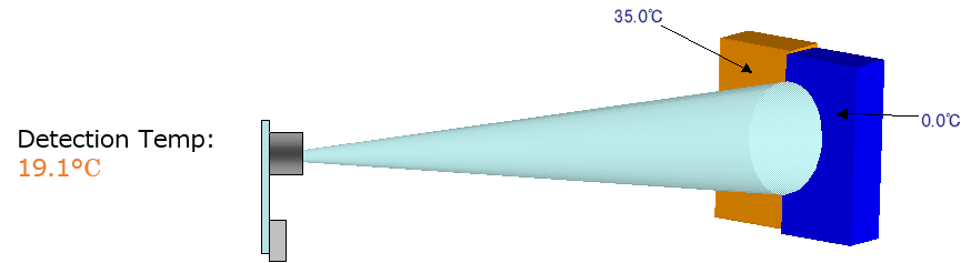
Fig 19: Relationship between Temperature Distribution and Output in the Detection Area
Recommended Circuit
A general application circuit for a thermopile sensor is configured to include an amplification unit.
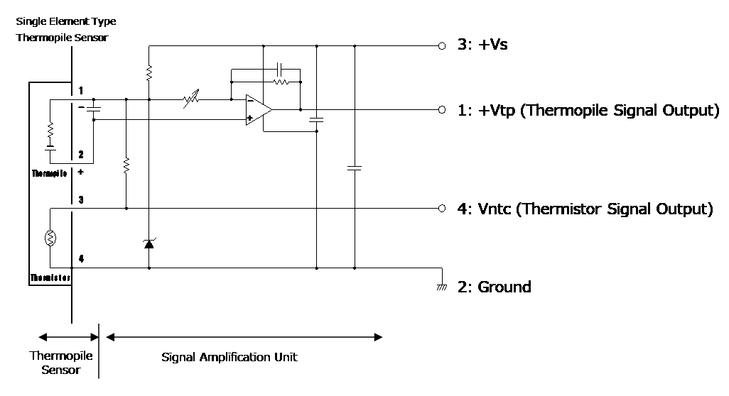
Fig 20: Recommended Application Circuit